Practical considerations on shaft runout

I have re-read an interesting article on shaft runout (‘Understanding and Mitigating Shaft runout ” – Orbit Magazine, 2005) for critical rotating equipment monitored trough proximity transducers (article considering both mechanical runout and electrical runout) and observed that it is plenty of room on improving the existing practices (at least in rotating equipment maintenance workshops).
Therefore, I took this opportunity to share with you some effective lessons learned on mechanical runout measurements, as recommended by API RP 687 “Recommended Practice – Rotor Repair”. Oh yeah, wise is he who’s learning from others ‘mistakes’…
Typical arrangement for measuring a rotor / shaft runout:
- The rotor (or its shaft) should be placed on v-blocks (or balancing machine) located at the bearing journals;
- The shaft end is positioned against a backstop to prevent axial movement during rotation. A ball bearing is typically placed between the shaft end and the backstop to prevent the shaft face from contacting the backstop. The rotor or shaft is also generally placed in the v-blocks with the bearing journal opposite the backstop slightly higher than the journal nearest the backstop. In this manner, the rotor will tend to thrust towards the backstop during rotation, preventing axial movement during the measurements;
- In addition, v-blocks should be lined with a material such as micarta or nylon and lubricated with a heavy oil (i.e. ISO VG 68 turbine oil) to prevent scoring of the journals;
- Furthermore, the v-block widths should be equal to at least one-half of the journal diameter, so that the contact with the journals is not localized in one small area. The entire length of the v-block shall be used for support in the center of the journal;
Sources of errors when measuring shaft runout:
- Errors due to incorrect dial gauge positioning. This error often encountered, both in workshop and field runout measurement, resulting in incorrect readings up to 30% (i.e. when dial indicator inclined to 45 degree – see Figure 1);
- Errors due to incorrect dial gauge setup (not positioned perpendicular to one v-block face). Notice when dial indicator is not perpendicular to one v-block face, a rotor shaft elliptical surface might not be observed during measurement (Figure 3);
- Errors due to hysteresis. Errors due to inconsistent runout measurements (i.e. turning the shaft in one direction, then perform another runout reading by rotating shaft in the other way due to stick slip phenomenon);

Figure 1 – Measurement error due to dial indicator setup (dial indicator reading will be only 70% of the actual shaft runout)

Figure 2 – Correct installation of dial gauge
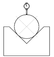
Figure 3 – Incorrect installation of dial indicator